Home- Blogs- Bearing Knowledge-Radial and Axial Load Capacity of Crossed Roller Bearings
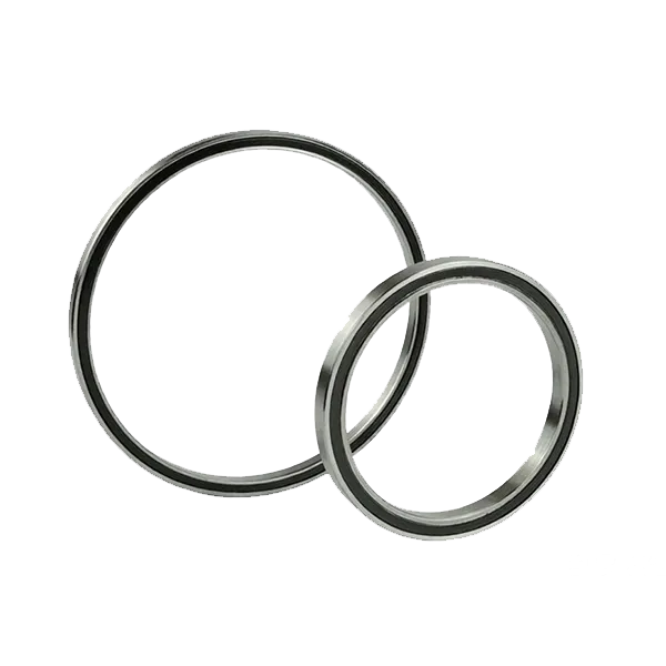
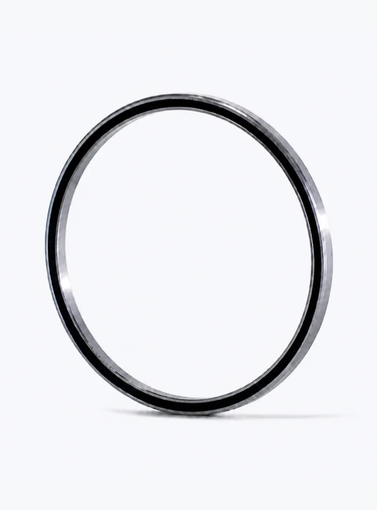
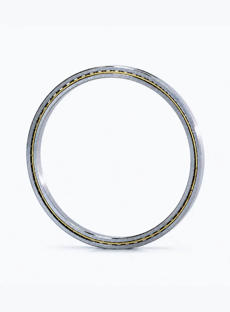
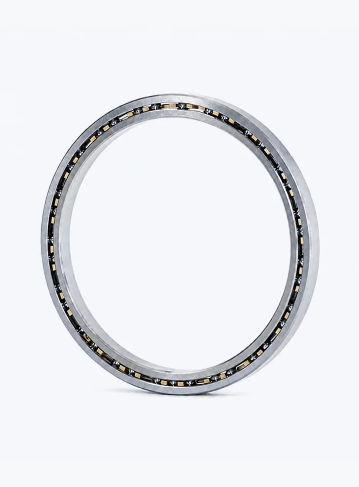
A crossed roller bearing carries load through cylindrical rollers set at 90 degrees to one another in alternating sequence between the inner and outer rings. Because the rollers are oriented at a 45 degree contact angle to the bearing axis, a single bearing set resists radial forces, axial forces in both directions, and tilting moments at the same time. That versatility is the reason crossed roller bearings appear in rotary tables, robot joints, machine tool spindles and indexing heads. It is also the reason their radial and axial load capacity must be evaluated together rather than separately, since both load components pass through the same contact.
Each roller contacts the raceways along a line rather than at a point. Line contact, combined with a large number of rollers spread across the full circumference, produces a stiff, high-capacity interface that distributes load evenly and limits deflection under reversing or oscillating motion.
The 45 degree contact angle is the defining feature. A force applied radially and a force applied axially of equal magnitude generate the same normal load at the contact. As a result, catalogue static ratings for radial and axial capacity in crossed roller bearings are usually of a similar order of magnitude, and the limiting factor is often not the raceway itself but the roller end faces, the guiding surfaces, or the rigidity of the surrounding structure.
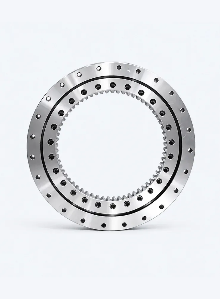
Radial capacity is governed by the number of rollers in contact, the effective roller length, the raceway hardness and surface finish, and the accuracy of the mounting surfaces. The theoretical rating published in a catalogue assumes ideal conditions: full 360 degree support from a rigid housing, uniform contact, and no edge loading.
Preload does not raise the static radial capacity of a crossed roller bearing. What it does is eliminate clearance, distribute load across more rollers at low external loads, and increase stiffness. The trade-off is a higher normal load at the contact for a given external force, which shortens fatigue life. Clearance produces the opposite effect: lower friction and easier rotation, but a smaller number of rollers carrying the load and greater deflection under reversing loads.
A thin-walled or flexible housing can deflect under load and transfer the force unevenly to a portion of the roller set. In practice, the radial capacity achieved in a real assembly is frequently lower than the catalogue figure because of housing deflection, poor flatness of the mounting face, or a shaft that bends under load.
Axial capacity is available in both directions from the same bearing. There is no need to pair two angular contact bearings back-to-back, and there is no axial clearance to adjust during assembly. The rollers transmit thrust through the same 45 degree contact that carries radial load.
Moment capacity is a distinct and often decisive characteristic of crossed roller bearings. Because the roller set spans a raceway diameter, an overturning moment is resisted by a force couple spread across that diameter. The larger the raceway diameter for a given cross section, the greater the moment that can be absorbed. This is why crossed roller bearings are the standard choice for rotary table and tilting axis applications where the load is applied off-centre.
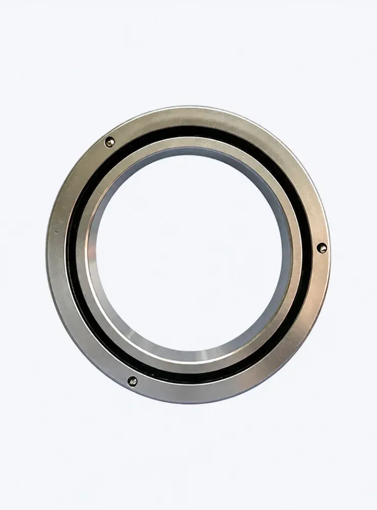
Catalogue data usually separates static and dynamic values, and understanding the difference prevents both oversizing and premature failure.
A common error is to check only the radial figure and ignore the combined effect. When radial and axial loads act simultaneously, they must be combined into an equivalent load before comparing against the rating.
The gap between catalogue values and installed performance comes from a small number of predictable sources:
Selection proceeds in a consistent sequence regardless of the application:
BIBO Bearing supplies crossed roller bearings across multiple series and cross-section sizes, and works with design teams to match the bearing to the load case rather than to a catalogue page alone. Sharing the load magnitudes, the moment arm, the mounting dimensions and the required stiffness allows the most economical bearing size to be identified before drawings are released.
Is radial load capacity equal to axial load capacity in a crossed roller bearing?
They are close in magnitude because both load directions act on the same 45 degree contact. The two figures are not always identical in a catalogue, because the practical limit for axial load may come from roller end contact and guiding surfaces rather than from raceway fatigue.
Does preload increase load capacity?
No. Preload increases stiffness and eliminates clearance, which improves positioning accuracy, but it reduces the load margin available for external forces.
Can one crossed roller bearing replace two angular contact bearings?
In many rotary table and robot joint designs, yes. A single crossed roller bearing handles radial load, bidirectional axial load and moment, which simplifies the housing and reduces stack height.
Radial and axial load capacity in a crossed roller bearing are not independent properties. They are two expressions of the same 45 degree contact geometry, and the real limit is set as much by the housing, the mounting accuracy and the lubrication as by the steel itself. Evaluating the combined load, the moment and the stiffness requirement together is what separates a bearing that performs for its full rating life from one that fails early.
Preload and Stiffness in Crossed Roller Bearings Explained
Crossed Roller Bearings vs Tapered Roller: Key Differences
Crossed Roller Bearings Precision Motion Guide
Crossed Roller Bearing vs Slewing Ring: Which to Use?
OEM vs Aftermarket Crossed Roller Bearings: What to Pick
How to Source Quality Crossed Roller Bearings in Bulk